A secondary component within the AFM is an air temperature sensor. The fuel injection computer responds to this sensor by leaning out the mixture for hotter intake air, or enriching it for colder intake air.
One other function of the wind vane mechanism is that it directly controls
the safety shutoff to the fuel pump. If there's no air flow through the AFM,
the vane should be completely closed. The fuel injection system was apparently
designed to assume that the engine must have stalled, as might happen in
an accident, and so in turn, the fuel pump is shut off so as not to continue
dumping fuel into a potentially compromised engine compartment.
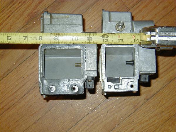
The GSL-SE AFM inlet is 2" x 2", yielding a 4 square inch cross sectional area to the inlet. Compare that to the total cross sectional area of the GSL-SE throttle body throats -- there's one 40 mm primary throat, and 2 36 mm secondary throats, as per the '85 Mazda shop manual (p. 30-4). Do the math right, and you'll come up with 5.1 sq. inches of total cross sectional area for the throttle body inlets. Just for comparison, the air flow meter's circular outlet has an inner diameter of 2 5/8", yielding a 5.4 sq. in. cross sectional area. One of these days, I'll measure some of the gaskets for the intake manifold and post those cross sectional areas here, too. But what we have so far makes it pretty apparent that it's the AFM inlet area that's strangling our little rotary race-horses here.
Now compare that GSL-SE AFM inlet to the 86-88 normally aspirated RX-7's AFM inlet, which is 2.5" x 2" -- that's 5 sq. inches. That seems like a pretty nice match for the GSL-SE's throttle body. Without flow bench testing, the best guess that I can offer is that the larger AFM will offer about 25% more flow potential than the smaller one. That estimate is based strictly on the 25% increased cross sectional area of the 2nd gen AFM over the GSL-SE AFM, so don't be misled into thinking that you will get 25% more horsepower from implementing this modification. Regardless, the larger AFM is likely to free up some horsepower. So the second generation, normally aspirated RX-7's AFM seems like a logical upgrade.
BTW, I should make it clear that we're referring to only the 86-88 normally aspirated RX-7 AFM. The later model, normally aspirated engines were equipped with a Bosch-style mass air flow sensor, which is totally incompatible with the GSL-SE fuel injection computer. I have no idea what type of system is on the turbo cars. (If you know, send me a message, and I'll give you a cut of the royalties from this web page.) But from this point on, for readability purposes, I'm going to refer to the 86-88 normally aspirated RX-7 AFM as "the second gen AFM."
Another thought to consider is that at least one rotorhead has stated that he thinks that the stock AFM should be sufficient. David Lane is running his Cartech Turbocharged GSL-SE with it, and producing 270 hp through an otherwise stock GSL-SE intake path. But in researching this project, I have found that Miata owners have also taken on this upgrade, and they've reported some significant findings of actual horsepower increases and bench-measured flow rates. (This is very significant, because the stock Miata AFM inlet is exactly the same size as the GSL-SE AFM's inlet. The electronics are different, though. More on that later.) At the low end, Randy Stocker reported a 4.1 hp increase on a stock 1.6 liter Miata engine, and 5.5 hp on a 1.8 liter early Miata. Randy also speculates, in that same article, that a modified Miata would likely see much greater gains, especially a 1.8 liter engine with significant modifications transplanted into an older Miata. Again, it's a good comparison, because a stock 1.8 liter Miata and a stock GSL-SE have similar horsepower, and are likely to have similar breathing requirements. Anyway, Randy did some flow-bench testing and found that his stock AFM would flow 165 cfm at normally aspirated pressures, and 300 cfm at pressures similar to what would be found on a 6 psi boosted early Miata. That explains why David Lane is doing fine with his stock AFM. Scrunch those air molecules closer together, and they're going to go through the pipe faster.
But what does all of this mean for those of us with modified GSL-SEs who
wish to use the 2nd gen AFM? If a stock Miata engine, which puts out about
the same horsepower as a stock GSL-SE, can gain 4 or 5 hp, how much more
of a gain will a street ported GSL-SE with exhaust and ignition mods realize?
I'm going to go out on a limb and guess that it might be as much as 10 hp,
but certainly not more. Turbocharged? This might well free up 20 hp. We won't
know until someone does it and visits a dyno.
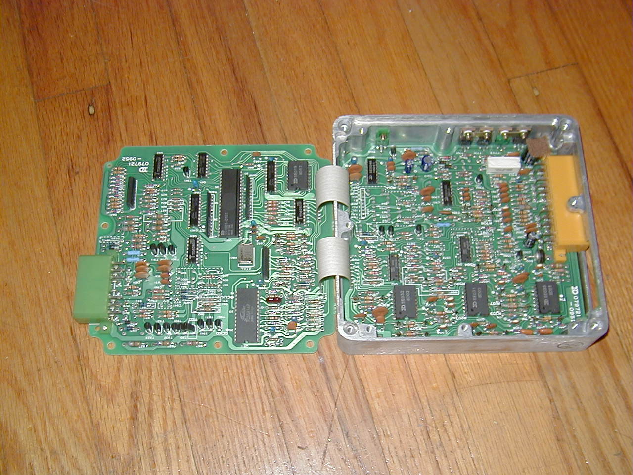
A little investigative surgery was in order, so I popped the covers off of both AFMs. The cover is a snap-in part, sealed with silicone caulking. Cut around the black cover with a razor, and you can pry it up with a screwdriver. Don't go too deep with the screwdriver, though. You wouldn't want to gouge the circuit board.
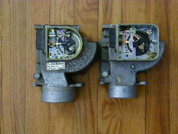
Comparing both AFMs side-by-side, it was obvious that the basic design is very similar. Both units have an armature that swings across a circuit board as the AFM's vane opens wider in response to the intake air flow. The armature contacts the circuit board over the entire arc of the armature's movement. The arc-shaped contact area is covered by sections of a black, conductive material, and it's apparent that this conductive material has varying electrical characteristics throughout it's range, forming a stepped potentiometer. That appears to be how the AFM sends the air flow signal back to the EFI computer.
Both AFMs have a spiral spring (clock-spring) that can be adjusted to vary
the mechanical resistance of the vane to airflow. Both AFMs also have an
electronic thermosensor that is visible from the outside of the AFM. It's
the little plastic piece in the front of the airflow tunnel, before the vane.
(See the AFM inlet photo, above.) The thermosensor is merely clipped onto
the back of the AFM wiring harness connector. The circuit board is soldered
to the wiring harness connector.
84/85 AFM Circuit (left) and 86 AFM Circuit (right):
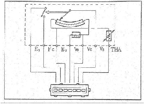
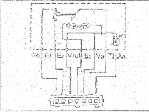
As I mentioned earlier, the Mazda shop manuals describe the electrical differences between the two AFMs. Some of the pinouts are completely compatible, but others have ranges that simply will not work without building some pretty slick circuitry to match the newer AFM to the older ECU. For example, pins 1 and 2 (facing the connector on the AFM, from the left) are basically an on/off switch for the fuel pump. The 84/85 manuals refer to these two signals as E1 and FC, on pins 1 and 2 respectively, but the 86 manual has E1 and FC on pins 2 and 1 -- swapped. That's no big deal, though -- a switch is a switch, so the fuel pump will run without modifying the ECU. That explains why those folks who have tried this already were able to get their cars to run, albeit poorly.
Pin 7 is also common to both as the thermosensor signal, but one manual refers to this as THA and the other as THAa. Thankfully, the resistances given for both thermosensors are identical, but the earlier manual lists an additional resistance value for a temperature of -20 degrees C, whereas the 86 manual doesn't cover that range. (Both manuals have listings for 0, 20, 40 and 60 degrees C.) Also note that both thermosensors are grounded with E2 at pin 3, but the 86 AFM links that E2 ground with pin 5 as well. (Pin 5 on the 84/85 AFM is for one of the variable signals that is sent to the ECU from the potentiometer in relation to the angle that the AFM door is open.) That's the first of the electrical incompatibilities between the two AFMs.
Pin 6 in both AFMs is a straight shot to the armature that swings along the conductive material, but there are different resistances specified between pins 6 and E2 for the two AFMs. Pin 4 in both cases seems to be an output signal from the potentiometer, but the ranges of resistance are again different.
One thing that you won't see in either manual is that the reference voltage is different between the two AFMs. Specifically, the 2nd gen AFM operates at 5 volts while the GSL-SE AFM operates at 12 volts. That information came from the 1986 Mazda (mechanic's) Training Manual - which goes through the differences between the previous version (GSL-SE) and the 2nd gen version of the car.
Electrical Engineers, this is your call to arms! This project cannot work with the stock electronics in place without YOU, Mr. EE, making a little black box that gets the AFM and ECU to talk to each other.
Incidentally, the Miata owners who have successfully done this swap don't
have any such concerns. The 1.6 liter Miata's AFM and the 2nd gen RX-7 AFM
are pin and electrically identical.
Both AFMs have their circuitry mounted on a steel plate. The mounting plates are different in both size and shape, and the mounting screws are in different locations, too. This will not merely drop in.
The circuit itself looks to be the same size on both units, and the radius of the conductive arc also appears to be the same. It's probably just glued onto the plate, in which case, it may be possible to remove each circuit to transfer the GSL-SE circuit to the 2nd gen plate. On the other hand, that glue might never let go, regardless of any prying and/or heating that you might implement to get it to release its grip.
The GSL-SE mounting plate is larger than the 2nd gen's. If the circuit cannot be unglued from the mounting plate, the plate will have to be removed and very precisely cut down to the size of the 2nd gen plate, paying careful attention so that mounting screw holes and the conductive arc in the finished product line up perfectly. Also, the wiring harness connector would have to be desoldered from each circuit board before this operation is started, and resoldered back in place when done. All of this could be tricky, but it does appear to be possible.
Even after successfully doing all of this, there's still some more work
to be done.
Filtering should also be pretty easy to accommodate, as there are already cone-style air filters which should attach to the 2nd gen AFM. Some thought should probably be given to fabricating a cold air intake box, but again, let's deal with this one step at a time.
The air funnel connection could have proven to be a major obstacle in this
project, but the Miata boys have come through for us in a big way here. Chris
Erbers was good enough to identify a Napa Auto Parts cooling hose that will
serve as a reducer from the 2nd gen AFM to the identically sized Miata air
funnel. Ask for NAPA part #8097. He doesn't explicitly say so, but I expect
that some kind of a connecting sleeve will be needed inside the seam between
this hose and the air funnel.
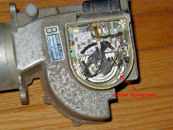
But the Miata boys have again identified a problem for us: during partial throttle changes -- anything but mashing the pedal to get into the full throttle fuel maps -- the calibration of the air flow meter spring is critical to eliminate mixture related power losses that occur between the instant of the throttle change and when the 02 sensor and ECU catch up to the engine's requirements. The mechanism for this adjustment is very simple -- adjust the wind-vane spring tighter (so as to close the vane more) to get leaner mixtures, and looser (for a more open vane) to get richer mixtures. The red arrow in the photo points to the adjusting point. Mark your starting point on the the spring's gear before making any changes!
Randy Stocker also suggests that off-idle throttle response can be affected
by adjusting the air bypass screw of the AFM. It's under the metal plug in
the top left of the photo.
That brings me to the disclaimer: DON'T try this at home! Don't try it on your friend's car, your mom's car, or even your pain-in-the-ass kid brother's car. Don't try it anywhere. In fact, don't even drive your car, at least not on my advice. If you hurt yourself or your property, you're on your own. Check and verify everything I've that said here, and do your own research and testing to make sure that nothing's going to go wrong.
Many people have contributed various bits of wisdom and information to this article. Much of the information here was compiled from over 80 e-mails that I've sent and received on this subject during the past three years since I started thinking about this project. Gary Gloceri, David Lane, David Randall, and Felix Miata are among the most notable electronic pen-pals to share their knowledge. Thanks guys.
Randy Stocker's web page was an invaluable resource for this project. It's "must reading" at http://members.aol.com/solomiata/airflowmtr.html. Randy deserves a medal for his efforts. Hopefully, someday, I'll be able to buy him a beer.
Chris Erber's page about his Miata AFM conversion is also well worth reading. See http://ourworld.compuserve.com/homepages/erbers/project/erbers/rx7afm.htm.
Bummer! I was hoping for all sorts of new screws to play around with.